Introduction
More than 70% of the earth is covered by water, which makes shipping historically the easiest and cheapest way of connecting manufactures and customers across the globe and can be reasonably considered to be the artery of the global economy. An enormous variety of goods, 90% of the total volume of global trade, from raw materials to sophisticated, expensive engineering units are shipped in a variety of forms, bulk, packed, containerized or unpacked, on a daily basis.
The main goal of any ocean shipment endeavor is to deliver the cargo to the consignee in quantity and quality as loaded, in order to do so all breakbulk cargoes have to be reasonably and sufficiently secured in order to sustain the passage through the harsh marine environment. Additionally, the securing of the cargo is not only vital for the cargo itself, but also for the transporting vessel, which can suffer structural damage, stability issues, or injuries of the persons on board due to shifting of cargoes in her holds.
The above issues have been recognized by the International Maritime Organization (IMO) and the maritime community and a special provision of SOLAS Chapter VI reg. 5, covering and enforcing requirements for stowage and securing of cargoes other than solid and liquid bulk has been adopted.
Further to the above, in order to assist the vessel’s owners, master, and administration, to set unified guidelines and to enhance the safety during loading, stowage, lashing and transportation of a variety of breakbulk cargos, IMO issue a Code of safe practice for cargo stowage and securing (CSS code), first adopted at 1991, consequently updated and amended through the years with last consolidated edition dated 2011 and last amendment MSC.1/Circ.1352/Rev.1 Dec.2014.
In this article, the securing of non-standardized, over-dimensional, project cargoes, etc. issue will be discussed. The matter is covered by part of the CSS code, namely Annex 13, which is dealing with the methodology for assessing the efficiency of securing arrangements for non-standardized cargo.
Section 1 – Maximum securing load
The maximum securing load (MSL) is a term used to define the load capacity for a device used to secure cargo to a ship. It is similar to the safe working load (SWL) and workload limit (WLL) used in the other sectors of the industry.
The MSL of the securing devices offer is labeled on the product itself as per below.
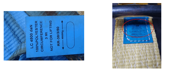
Figure 1: Typical web lashing MSL marking
In case not stated it can be found from the certified breaking strength taken from the manufacturer certificate or marked on the securing device, following the below tables.
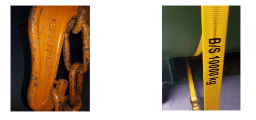
Figure 2: Typical MBL marking on lashing devices
| Material | MSL | |
| Shackles, rings, pad-eyes, turnbuckles of mild steel | 50% of breaking strength | |
| Fiber rope | 33% of breaking strength | |
| Web lashing | 50% of breaking strength | |
| Wire rope (single use) | 80% of breaking strength | |
| Wire rope (re-useable) | 30% of breaking strength | |
| Steel band (single use) | 70% of breaking strength | |
| Chains | 50% of breaking strength |
Table 1: Determination of MSL from breaking strength (CSS code,2011 p.51)
The MSL of timber should be taken as 0.3 kN/cm² normal to the grain.
Section 2 – Accelerations
In order to calculate the restraint forces required and the sea-fastening arrangement to prevent the cargo shift due to the vessel’s motion, the acceleration forces experienced by the cargo need to be determined.
When the ship is at sea, she has the freedom to perform all six types of motions (linear and rotational) around her longitudinal, transverse, and vertical axes. The rolling, pitching, and yaw are the three rotational motions and sway, surge, and heave are the linear motions experienced by the vessel. The magnitude of each of them depends on a number of factors – wind and sea condition, heading and speed of the vessel, type and size of the vessel, vessel stability and loading condition, shape of the underwater and windage areas, etc.
Combining the above it can be summarized that on every item onboard the vessel, three forces are acting, perpendicular to each other in the vertical, athwartships, and fore-and-aft line.
Further, it has to be taken into account that the acceleration forces are not identical at different points of the ship. Ex. cargo stowed in lower hold midship of the vessel will experience almost twice lesser acceleration, than if it has been stowed on the forward part of No. 1 hatch cover.
For some special project, valuables cargoes, special vessel, etc. the acceleration experienced by the cargoes are calculated based on 50/100 years historical weather data for the expected passage and time of the year, the loading and stability condition of the vessel/transport unit, the location of the cargoes, etc.
For most of the cargoes, shipped on a regular basis on-board an ocean-going vessel, performing a detailed motion analysis may be an unnecessary luxury. In such cases, the CSS code provides a quick methodology for calculating the accelerations experienced by cargoes with the following limitations:
- Operation in an unrestricted area;
- Operation during the whole year;
- Duration of the voyage is 25 days;
- Length of the ship is 100 m;
- Service speed is 15 knots;
- B/GM > 13 (B = breadth of ship, GM = metacentric height).
The basic acceleration experienced in different points of the ship based on the above remarks can be found in the table below:
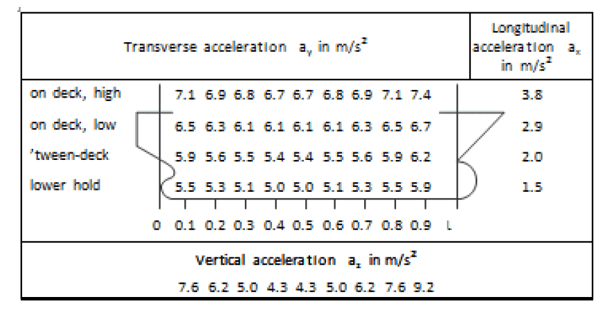
Table 2: Basic accelerations (CSS code,2011 p.52)
In order to make the calculations more precise additional the accelerations extracted from the above table have to be corrected for the difference in vessel length, speed, and B/GM less than 13.
For ships of lengths other than 100m and a service speed other than 15 knots, the acceleration figures should be corrected by a factor given in Table 3.
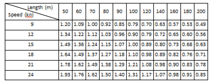
Table 3: Correction factors for length and speed (CSS code,2011 p.53)
For not tabulated length/speed combinations, the following formula may be used to obtain the correction factor:
![]()
v = speed in knots
L = length between perpendiculars in meters
This formula shall not be used for ship lengths less than 50 m or more than 300m.
In addition, for ships with B/GM-less than 13, the transverse acceleration figures should be corrected by a factor given in Table 4.
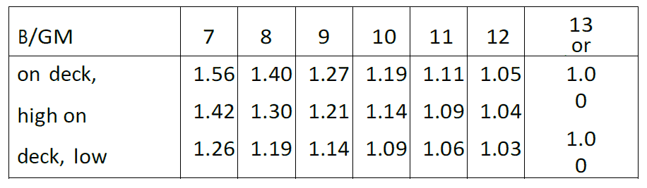
Table 4: Correction factors for B/GM < 13 (CSS code,2011 p.53)
Section 3 – Wind and sea forces
In case the cargo is stowed on deck, additional forces due to wind and green-seas on deck can be expected based on the position of the cargo, vessel freeboard, etc.
In order to determine the wind pressure experienced by the cargo, which is stowed on/above the weather deck the Longitudinal and Transverse wind-exposed area in square meters has to be calculated. A simple approach calculation is to assume that on every square meter expose area, the force acting is 1 kN. So, in order to calculate the Longitudinal (Fwx) and Transverse (Fwy) wind force the relevant expose area has to be multiplied by 1 kN.
Green seas washing over the deck can have an effect on any deck cargo stowed in close proximity to the vessel’s side. In case an enormous quantity of water is shipped on deck, the forces induced by the waves to the cargo can be severe and unavoidable damages to the lashing and the cargo will occur. The below method considers that all reasonable precaution measures for reducing the green-seas on deck are taken in a timely manner. Sea sloshing forces need only be applied to a height of deck cargo up to 2m above the weather deck or hatch top. For voyages in a restricted area, sea sloshing forces may be neglected.
The method for calculating the effect of the water shipped on deck is similar to the method used for wind force calculation. First, we calculate the Longitudinal and Transverse exposed areas, which do not include the whole height of the cargo but only up to 2m and second multiply the expose areas by 1 kN, in order to find the forces in the Longitudinal (Fsx) and Transverse (Fsy) directions.
Section 4 – Friction
Positioning the cargo on top of dunnage has the following positive effects:
- A more uniform spread of the cargo load on the deck and vessel structural members;
- Adding friction between the cargo and the deck, which contribute to preventing of sliding;
The friction coefficient for different surfaces recognized and used in the industry can be found in the below table.
| Materials in contact | Friction coefficient (μ) |
| Timber–timber, wet or dry | 0,4 |
| Steel–timber or steel– | 0,3 |
| rubber Steel–steel, dry | 0,1 |
| Steel–steel, wet | 0,0 |
Table 5: Friction coefficients (CSS code,2011 p.54)
On some occasions due to different reasons, a special rubber mats dunnage is used, in which friction coefficient is between 0,5 – 0,8.
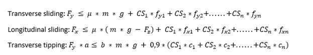
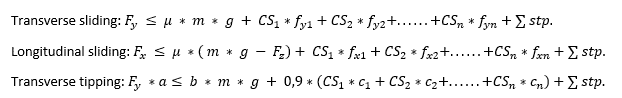
Section 5 – Advanced calculation method
Transverse sliding
In order to calculate the required lashing on each side a balance of forces calculation has to meet the following inequality:
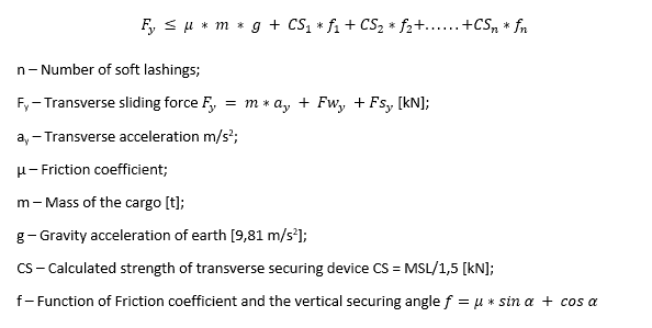
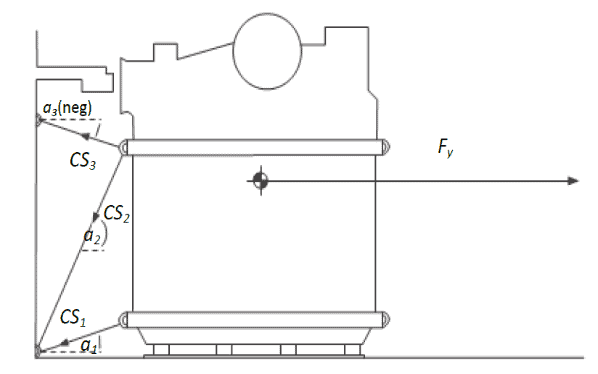
Figure 3: Balance of transverse forces (CSS code,2011 p.55)
For any soft lashing, the following have to be taken under consideration:
- A vertical securing angle greater than 60⁰ will reduce the effectiveness of this particular securing device with respect to the sliding of the unit. Disregarding of such devices from the balance of forces should be considered unless the necessary load is gained by the imminent tendency to tipping or by a reliable pre-tensioning of the securing device and maintaining the pretension throughout the voyage.
- Any horizontal securing angle, i.e. deviation from the transverse direction, should not exceed 30⁰, otherwise, exclusion of this securing device from the transverse sliding balance should be considered.
-
Transverse tipping
In order to calculate the required lashing on each side a balance of forces calculation has to meet the following inequality:
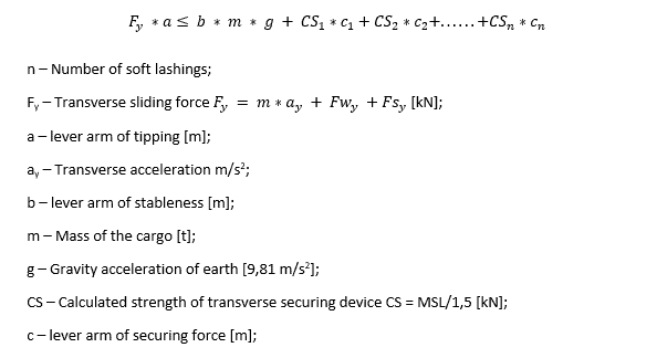
Figure 4: Balance of transverse moment (CSS code,2011 p.56)
Note: The length of the lever (c) from the tipping axis to the lashing can be assumed to be equal to the width of the cargo unit if the lashing is connected to the deck and to the high point of the cargo.
-
Longitudinal sliding
Generally, the transverse securing devices provide sufficient longitudinal components to prevent longitudinal sliding. In order to ensure the above the balance of forces calculation has to meet the following inequality:
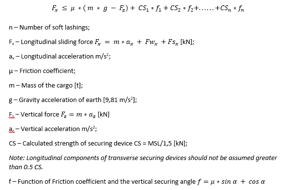
Note: It is a good practice that only lashings which are at an angle of more than 20° to the athwartship line should be used in the calculation.
Section 6 – Alternative method
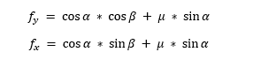
In the above-presented method for calculation, only the vertical securing angle is taken into consideration. For more precise calculation the horizontal securing angle has to be taken under consideration too.
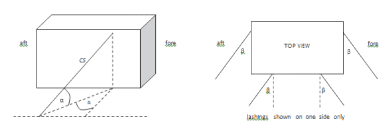
Figure 5: Definition of the vertical and horizontal securing angles of α and β (CSS code,2011 p.57)
The calculations are the same as described in the Advance method with the following additional remark:
- The safety factor for calculated strength of securing device (CS) is 1,35 CS = MSL/1,35 [kN]
- Securing devices which have a vertical angle α of less than 45⁰ in combination with horizontal angle β greater than 45⁰ should not be used in the balance of transverse tipping.
In order to restrain the Transverse sliding, Transverse tipping, Longitudinal sliding the balance of forces calculations has to meet the following inequalities:
Most of the parameters of the inequalities have been discussed in the foregoing points. The new parameters are only fx and fy, which are functions of friction coefficient, vertical and horizontal securing angles.
Disclaimer: This post is not meant to be authoritative writing on the topic presented. thenavalarch bears no responsibility for the accuracy of this article, or for any incidents/losses arising due to the use of the information in this article in any operation. It is recommended to seek professional advice before executing any activity which draws on information mentioned in this post. All the figures, drawings, and pictures are property of thenavalarch except where indicated, and may not be copied or distributed without permission.
TRANSPORT VESSELS FOR FLOATING WIND
By Alan Crowle, BSc, MSc, CEng, CMarEng, FRINA, FMAREST, FSCMS Masters by Researcher, University of Exeter, College of Engineering, Mathematics and Physical Sciences, Renewable Energy Group SUMMARY Floating wind turbine construction is a large logistical exercise. The...
Using simple tools for efficient Passage Planning for seagoing vessels
Introduction Planning a vessel’s voyage is a critical detailed exercise, and the main goal is to ensure safe and efficient passage between two ports. The Master has the responsibility for the vessel voyage planning, but very often he delegates the actual voyage...
Designing a closed chock as per IACS rules
Introduction Chocks are used universally for mooring and towing operations on ships. For towing operations, Chocks are used for guiding the towing rope from the winch through the outer shell of the vessel to the tug. For mooring operations, the chock is used to...
The Optim22 Method of Weight Optimization of Framed Steel Structures
1 Abstract A semi-automated structural weight optimization system is presented for framed structures of post and beam construction which is based on basic structural member design principles. The approach is to adjust member properties in a manner that...
How to identify the spoolpiece lifting points?
In the offshore construction industry, the connection between the newly installed pipeline and the riser is accomplished via a series of ‘spoolpieces’ (or spools). The spool is fabricated by welding pipe joints to form an L-shaped, Z-shaped, or possibly a straight...
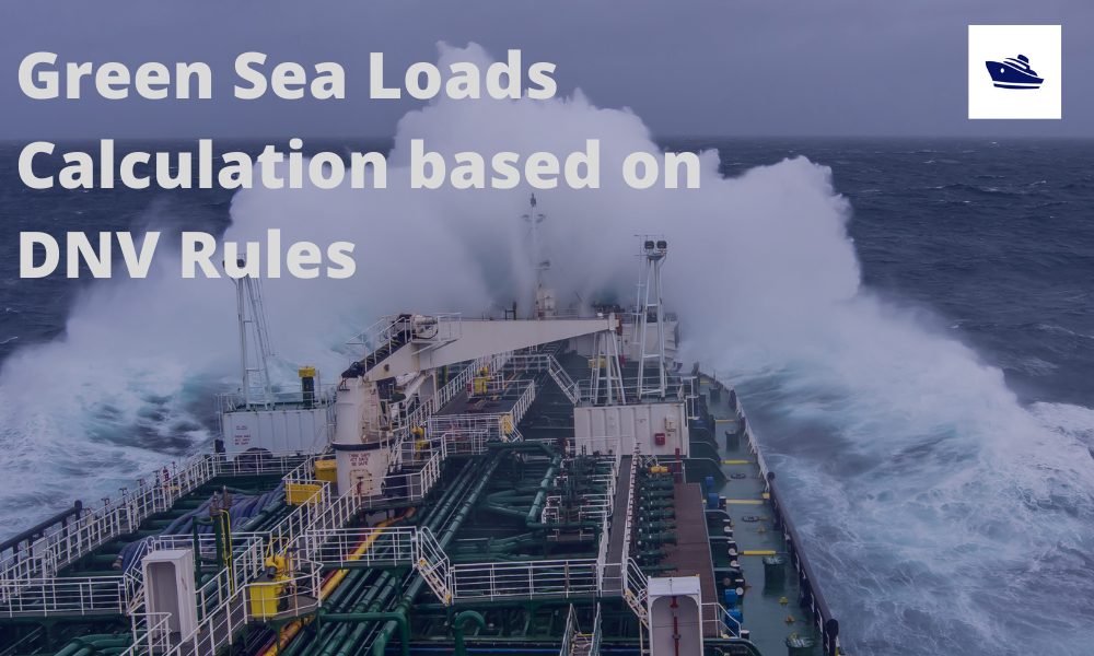
Sea Pressure Loads Calculation based on DNV Rules
Introduction Sea pressure loads are an important factor in the structural design of a vessel. What is sea pressure load? As the term suggests, it is the external pressure on the vessel due to the surrounding sea. What kind of pressure it is, and how to...
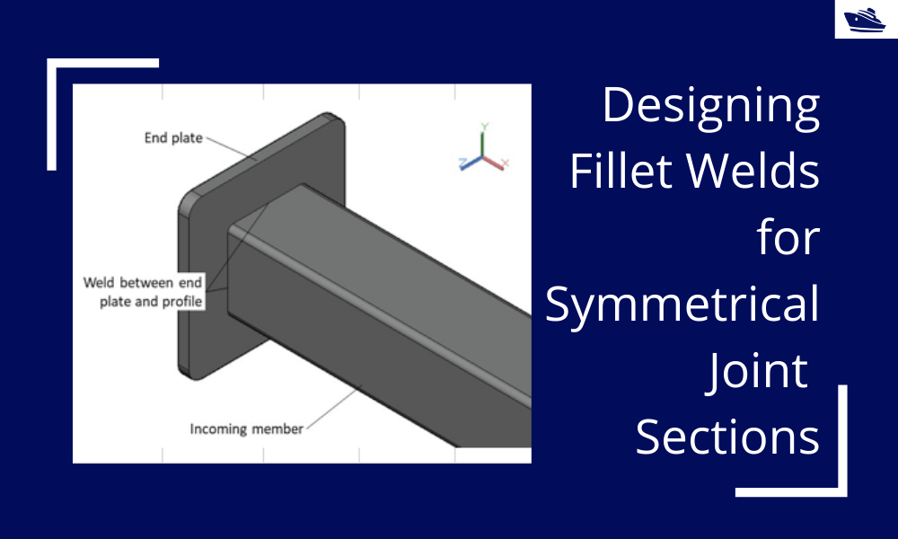
Designing Fillet Welds for Symmetrical Joint Sections
Introduction Fillet welds are the most commonly used weld types in marine structures. A fillet weld is used when there are two pieces of metal that are joined perpendicular to each other or at an angle. In this article, we will explore how to select the right size...
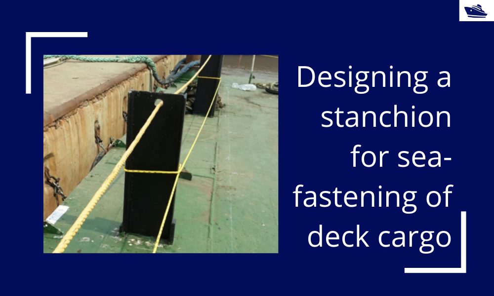
Designing a stanchion/stopper for sea-fastening of deck cargo
Introduction Stanchions – a familiar term for mariners and ship designers. What are Stanchions? A stanchion is generally a vertical pipe or beam which is used to support some structural item or provide support rails on the deck. In ships, the most common type of...
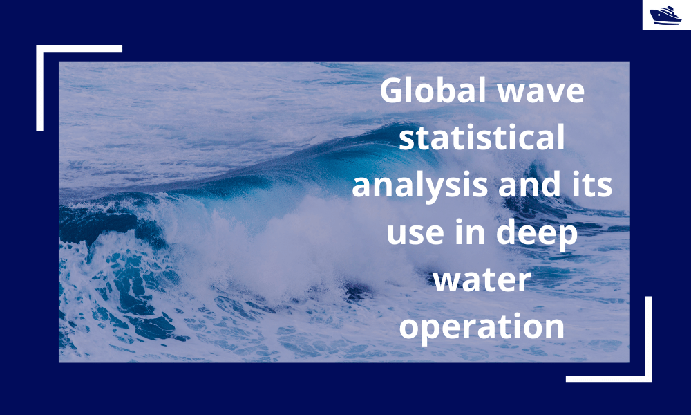
Global wave statistical analysis and its use in deepwater operations
Why do we need wave analysis? For the design of offshore operations such as installation and transport of offshore structures, as well as lifecycle design of floating and fixed structures, knowledge of extreme waves as well as the probability of different sea-states...
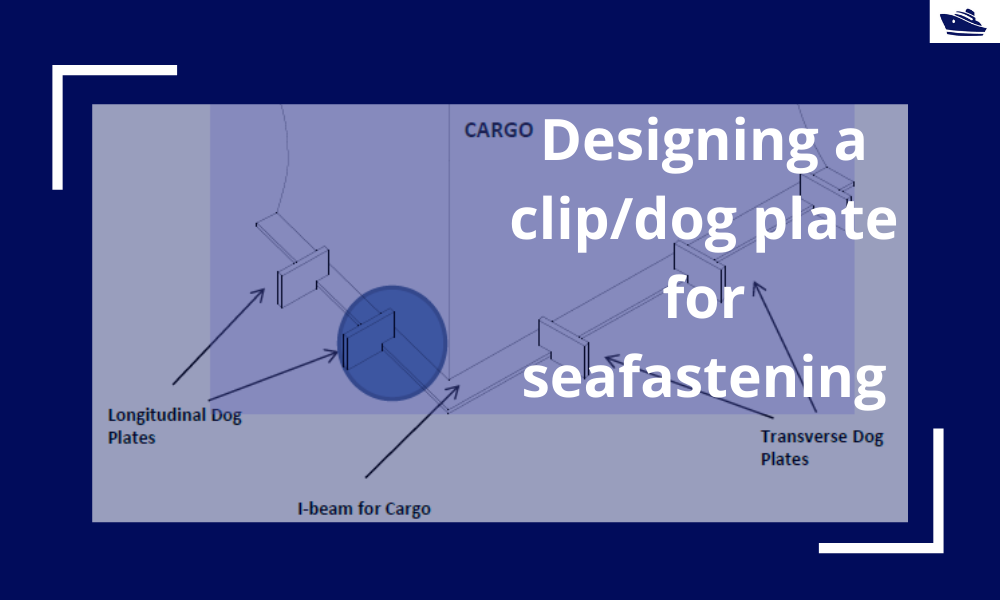
Designing a clip/dog plate for seafastening
Introduction In an earlier article, we saw how to design stoppers for seafastening. Stoppers are items that are used to contain the translation movements (longitudinal and transverse directions) of a cargo on the deck/hold of a vessel. That brings us to the question –...
dear sir
good day
if there is a spreadsheet for Designing the lashings of deck cargo using IMO CSS or not ?
best regards
Hi Ezzat
Yes, due to be launched soon
Nicely combined essential information. Do you have any application for calculations?
Thanks Georgiy
Yes, we do have one application for 4-point lashing, and another one (generic one) being launched on 23rd July
https://thenavalarch.com/software/marine-transportation/lashing-design-4-point-lashing-imo-css/
Very good and compressed material.