
CATHODIC PROTECTION ON SHIPS – SACRIFICIAL ANODES

Image Source: pixabay
SECTION 1 – INTRODUCTION
Due to the environment in which they operate, ships are among the structures most exposed to environmental corrosion. The sea water is a very corrosive environment because the salt present in it makes it a very good conductor of electricity. It creates a lot of free ions which accelerate oxidation of iron (mild steel) which ships are made of. This oxidation creates what we know as rust.
Almost every part of the ship is subjected to corrosion, with varying intensity. Parts of the vessel underwater or exposed to water (e.g. ballast tanks and pipes) are more affected by corrosion. Some of the parts highly exposed to corrosion by sea water are
- Ship’s external hull – exposed to water
- Rudder
- Propeller shaft
- Bilge Keel
- Bow Thruster
- Cargo Tanks
- Ballast Tanks
- Other tanks
- Pipes carrying ballast/cargo
There are various methods of protecting the ship hull and other areas from corrosion. The selected method depends on the area to be protected, its shape and its environment.
There are three major methods of corrosion protection
- Anti-corrosion paints – metallic/organic
- Cathodic Protection – ICCP (Impressed Current Cathodic Protection)
- Cathodic Protection – Sacrificial Anodes
In this article, we will discuss one of such methods: Cathodic Protection using Sacrificial Anodes
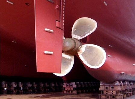
Anodes on a hull and rudder (source www.cathodicme.com)
SECTION 2 – CATHODIC PROTECTION USING SACRIFICIAL ANODES: THE BASICS
2.1 What is Cathodic Protection?
Cathodic protection is a mechanism which is employed to protect the ship’s surface from corrosion. As the name suggests, it has something to do with ‘Cathode’. What is a Cathode, and how does it protect a ship from getting corroded? For this we will have to get a little bit into the mechanism of corrosion.
How does corrosion take place in ships?
Ships are made of steel; whose main component is iron. Iron is an electrochemically positive element, i.e., it has a tendency to give up electrons to become a free ion. Sea water is composed of oxygen and hydrogen, and it produces electrochemically negative hydroxyl ions which can accept the electrons given by Iron. This way the Iron ions combine with the hydroxyl ions of water to form Iron Hydroxide. This is called the oxidization of Iron, and this oxide is what we call as the brown color rust.

The-mechanism-of-Corrosion-TheNavalArch
The mechanism of Corrosion (source www.zoombd24.com)
This youtube video gives a good picture of how corrosion occurs:
https://www.youtube.com/watch?v=cIGJX3PfIsY
2.2 The galvanic series
The galvanic series is a series which rates metals based on how readily they give up electrons to become ions. This is measured in terms of ‘Electrode Potential’. The table below shows the rating of different metals. The ones with more negative electrode potential are more likely to give up electrons and get corroded.

The-galvanic-series-TheNavalArch
The galvanic series (Source www.nordhavn.com)
2.3 The BIG idea!

Looking at the table above gives us an idea. The elements like Aluminium, Zinc and Magnesium are higher up than Steel on the scale (i.e., more negative). This means they are more ready to give up electrons and get corroded compared to Steel.
What if we introduce a Zinc bar and place it on the steel? The Zinc will get corroded first instead of the Steel, protecting the Steel, right?
This is the entire concept of Cathodic protection. When such an arrangement is used, the item which is being protected (i.e., ship’s steel) is called Cathode, and the one which sacrifices itself to protect the cathode is called Anode. Anodes are more electrochemically negative, and they save the Steel by getting corroded first.
The Steel is converted to a ‘Cathode’, and so this method of protecting the Steel from corrosion is called ‘Cathodic Protection’.
SECTION 3 – ABOUT SACRIFICIAL ANODES
Now let’s move on to learn about these anodes and how they are used for Cathodic Protection. Till now we know that we can use Zinc, Aluminium and Magnesium for becoming sacrificial anodes. Generally, for ships, Aluminium and Zinc are used.
How do these anodes look? Where do we place them on the ship? How many of them are needed?
3.1 Sacrificial Anodes – the basics
The basic idea of using sacrificial anodes is to use a metal like Zinc/Aluminium and create its contact with the surface to be protected.
The simplest picture which comes to mind is simply using a flat bar of the metal and fix it to the surface to be protected. This is actually the method commonly used to protect the outer ship’s hull.
We will next discuss the geometry and classification of anodes
3.1.1 Geometry of an anode
A simple anode will have two parts: the anode body and the anode insert. The anode body is the actual sacrificial material of the anode (Zinc or Aluminium), while the insert is generally flat bar or tubular, and made of steel. The insert is used to secure the anode to the surface to be protected using welding or bolting. Following figure illustrates the parts:
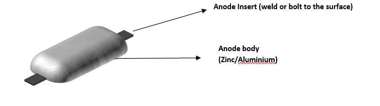
Geometry of an anode (source www.stoprust.com- edited by thenavalarch)
3.1.2 Anode Classification
We will discuss now the classification of anodes. Anodes can be classified based on their shape, size, material, mounting method and method of securing to the surface to be protected.
3.1.2.1 Anode Shape
Following are some widely used shapes for anodes
- Flat or block shaped
- Cylindrical or semi-cylindrical
- Tear-drop anodes
- Bracelet anodes
- Disc shaped
- Tubular anodes
Anodes can be of different shapes based on their applicability. The selection of the shape of anode depends on several factors. Some of these factors are:
- shape of the surface to be protected,
- availability of space,
- accessibility,
- ease of installation
- special considerations, e.g., effect on resistance for small boats
For example, flat anodes are used mostly for flat, large surfaces like the ship’s hull. Tear-drop anodes are used in high speed boats where streamlining of water is important as flat anodes will increase the boat’s resistance. Bracelet anodes are used for pipelines and propeller shaft, while tubular anodes are used for cables. There are no fixed rules here though, and the choice depends on the availability, cost and flexibility in design. For example, cylindrical anodes can also be used to protect pipelines, and it is not necessary to use bracelet anodes if they are costlier.
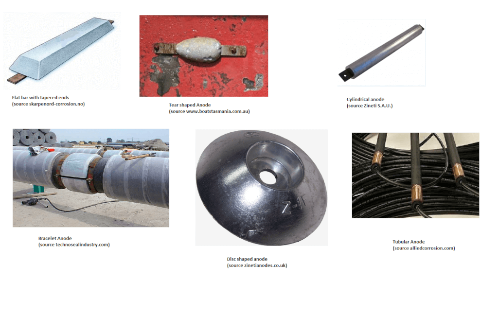
Different anode shapes
3.1.2.2 Anode Size
Anodes can be big or small sized, and this affects their weight and the overall weight of the structure to be protected. What size anode to select also depends on many factors, some of them being
- Size and shape of area to be protected – the hull can take large sized anodes, while a small rudder may not be able to accommodate the same sized anodes
- Space availability and accessibility – for example, the web or flange of a girder has less space available, and it cannot take big sized anodes
- Structural strength considerations – for a longitudinal, installing a single big sized anode may lead to a point load if the anode is too big, compared to several small sized anodes which will apply a distributed load
3.1.2.3 Anode Material
Usually for marine applications, Zinc or Aluminium anodes are deployed. Zinc has been traditionally used for corrosion protection, though Aluminium is now widely used. The two properties which measure performance of an anode are listed below.
- Closed Circuit Potential – the first parameter, Closed Circuit Potential signifies the ease with which the anode will be corroded. The more negative the value, the more readily the anode will get corroded. Generally, a potential of less than -0.08 Volts is required for cathodic protection of shipbuilding steel to be effective.
- Electrochemical Capacity (in Amp-hr/kg) – The second parameter, the Electrochemical Capacity, signifies the rate at which the anode material will be consumed.
The two parameters for Zinc and Aluminium are listed in the table below:
| Parameter | Aluminium | Zinc |
| Closed Circuit Potential | -1.1 V | -1.05 V |
| Electrochemical Capacity (Ah/kg) | 2000 | 780 |
Properties of Anode Materials (Source: DNV RP-B401)
We can see from the above table that Aluminium has a higher closed circuit potential – so it will more readily start working compared to Zinc. It also has higher Electro-chemical capacity compared to Zinc, and will be longer lasting for the same anode size.
Further, in fresh water application, Zinc tends to develop a calcareous coating on the anode surface, which prevents their effective working.
However, Zinc anodes have sometimes been found more reliable in environments with low oxygen, e.g., marine sediments or areas with high bacterial activity. Thus, while Aluminium is the more efficient one, Zinc may be more effective in some cases.
Further, Aluminium anodes, if falling from a height on oxidized steel, can create sparks. Thus they are nor recommended to be used inside cargo tanks of tankers. The maximum height above tank bottom which they must be placed is 28/W meters, where W is the weight of the anode in kgs.
Hence, the selection of the material depends on the type of environment it is going to be used, and should be carefully carried out.
3.1.2.4 Anode Mounting Method
The next important consideration for installation of anodes is the mounting method, i.e., the configuration of the tubular insert, and the positioning of the anode vis-à-vis the surface to be protected.
Based on mounting technique, there are two major types of anodes which are used in ships:
- Flush mounted anodes – in this type of anode, the anode material (Aluminium or Zinc) is in direct contact with the surface to be protected. The insert is generally a flat bar which can be welded or bolted to the surface.

A Flush Mounted Anode (source archive.hnsa.org)
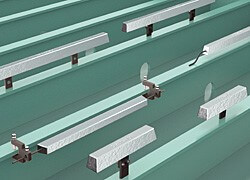
- Slender stand-off anodes – In these types of anodes, the anode material is not in direct contact with the surface to be protected, and there is a gap (hence the name stand-off). The insert is generally a tubular one which can be welded or bolted to the surface.
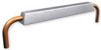
A stand-off anode (source www.acp.no)
One question arises, why do we need stand-off anodes, and why not flush anodes everywhere? What is the benefit of stand-off design?
The benefit of a stand-off design is that it is a more compact design, and the anode material is better utilized in a stand-off design. This is quantified by a parameter called ‘anode utilization factor’. This is the fraction of the anode material which is actually utilized over the lifetime of the anode. For flush anodes, this is around 80%, while for stand-off anodes it is 85 to 90%. Thus, stand-off anodes are better utilized over their lifetime.
Further, in case of flush anodes, due to constant contact between the anode material and the surface, the surface may suffer from embrittlement caused by deposition of ions from the anode material to the cathode (the protected surface).
That said, stand-off anodes protrude from the surface on which they are installed. When used on external hull of a vessel, these affect the streamlined shape of the vessel, and lead to increased drag and higher powering requirements. In comparison, flush anodes are closer and more compliant to the vessel’s geometric shape and have lower effect on resistance. Thus, flush anodes are usually preferred on outer hull due to their low drag properties.
Both Flush mounted and slender stand-off anodes are further classified into Short and Long, depending on their ratio of length to width. The length affects the resistivity of the anode and thus its current capacity.

3.1.2.5 Method of Securing the anode to the surface to be protected
There are three basic methods of securing the anode to the surface which is to be protected. They are
- Welding
- Bolting
- Using studs/brackets
Welding ensures the closest electrical contact between the anode and surface to be protected, thus ensuring good conductivity between anode and the surface through the insert material. However, due to issues of accessibility, some locations (e.g., stringers, girders etc.) may not be conducive to welding, and bolting or bracket installations may be preferred. Additionally, if the anodes have to be replaced relatively frequently, then bolted ones are relatively easier to replace compared to welded ones. Anodes can also be bolted to small studs or brackets which in turn are welded to the hull.

Welded Anode (source firtech-marine.com)

Bolted Anode (source www.boatstasmania.com.au)
Bracketed anodes in tanks (Source cathwell.com)
Now that we know about anodes and their basic properties, in the next section we will discuss about how to estimate the number of anodes required for protecting a surface (e.g., the ship’s hull or tanks)
SECTION 4 – HOW TO CALCULATE THE QUANTITY OF ANODES REQUIRED
In this section, we will see how we can calculate the number of anodes needed for protecting a surface. For this calculation, we will be following the DNV-RP-B-401, which details the procedure.
Before we get into actual formulas, it will be pertinent to understand what the anode is doing and how it is protecting the surface. Some concepts are presented below.
4.1 Current demand of surface to be protected
The anode, when connected to a surface, sets up an electrical circuit and current flows from cathode to the anode.
Each surface to be protected will need a minimum amount of current to flow for adequate protection. This is called the ‘current demand’ of the surface to be protected.
It is measured in terms of the amount of current required for protection of a unit area of the surface, also called as current density. The current demand of a surface depends upon many factors, like
- Dissolved oxygen content in water
- Marine growth
- Temperature
- Salinity
If the required current density for the Surface to be protected is iC, and the area of the surface is AS, then the total current demand of the surface will be
IC = iC x AS
4.1.1 Initial, Final and Mean Current Demands
The current demand of the protection surface also varies during its lifetime. Initially, when anodes are installed, then the surface metal is bare and fresh. The initial current demand will be the amount of current required to effect polarization of the bare metal surface in a short time-frame for protection to begin. This is called the initial current demand.
However, overtime, the surface develops calcareous deposits (due to cathodic protection), and also marine growth. These act as a deterrent to corrosion and thus reduce the current demand. When the anodes are close to depletion, then the current required to initiate protection in a short time-frame is called the final current demand.
Once Cathodic Protection is in action over a long time, then the Cathode potential becomes more negative, and the Cathodic Protection (CP) system is said to have reached a steady-state. This is called cathodic polarization, and it reduces the current demand over the operational life of the structure. The current demand during the steady state is called the mean current demand.
Here we need to note the difference between the initial/final and mean current demands. While initial/final current demands are the currents required to initiate Cathodic Protection, the mean current demand is the current required for the Cathodic Protection to keep operating during the lifetime of the anode. The mean current demand is around 50% of initial/final current demands, since the Cathodic Polarization leads to more negative cathodic potential, reducing the current needed for CP to keep working.
Since current demand is measured in terms of current density, we will adopt the following symbols and formulae for the initial, mean and final current demands
Initial Current Demand, Ici = ici x AC, where ici = Initial Current Density, AC = Area of protection surface
Mean Current Demand, Icm = icm x AC, where icm = Mean Current Density, AC = Area of protection surface
Final Current Demand, Icf = icf x AC, where icf = Final Current Density, AC = Area of protection surface
DNV RP-B401 provides the recommended values of the Initial, Final and Mean current densities as per the table below

Recommended Initial, Final and Mean Current Densities as per DNV RP-B401
4.2 Coating Breakdown Factor
The second important concept here is the coating breakdown factor. When a surface is coated with an electrically insulating coating (epoxy, polyurethane or vinyl based), then this provides additional protection against corrosion and reduces the current demand.
The factor by which the coating reduces the current demand of a structure is called coating breakdown factor. Its value lies between 0 and 1. A value of 0 means that the coating is 100% insulating, and a value of 1 means that the coating provides no current reduction.
The extent of reduction in current demand is dependent on the type of coating and the water depth at which the structure is installed.
There are different types of coatings as prescribed in DNV-RP-B401
Category I One layer of epoxy paint coating, min. 20 μm nominal DFT
Category II One or more layers of marine paint coating (epoxy, polyurethane or vinyl based), total nominal DFT min. 250 μm.
Category III Two or more layers of marine paint coating (epoxy, polyurethane or vinyl based), total nominal DFT min. 350 μm.
*DFT = Dry Film Thickness
The coating breakdown factor if given by
f = a + b.t
where t is the coating age and a, b are factors determined from DNV-RP-B401
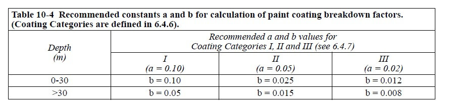
Coating breakdown factors (source DNV-RP-B401)
The coating breakdown factor is different for initial, final and mean phases (since ‘t’ is different for each), and is to be calculated separately for each stage.
4.3 Current demand including coating breakdown
After incorporating the coating breakdown factors, the initial, mean and final current demands can be written as
Initial Current Demand, Ici = ici x fci x AC, where fci = initial coating breakdown factor
Mean Current Demand, Icm = icm x fcm x AC, where fcm = mean coating breakdown factor
Final Current Demand, Icf = icf x fcf x AC, where fcf = = final coating breakdown factor
At this stage, we know what current demand of the surface to be protected is, and how we calculate this current demand. Let’s now look into the critical properties of anode which help us in the calculation of number of anodes needed.
4.4 Anode Properties and Concepts
4.4.1 Resistance of Anode
The resistance of anode is simply a function of the anode dimensions, the anode geometry and the resistivity of the seawater. Seawater resistivity depends on the temperature and salinity of the sea water. A graph for determining Seawater resistivity is provided in DNV-RP-B401
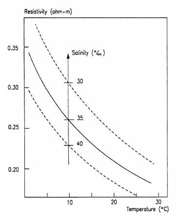
Seawater Resistivity as function of Temperature for salinity between 30-40% (Source DNV-RP-B401)
Depending on the type of anode, there are different formulae to calculate the resistance of anode
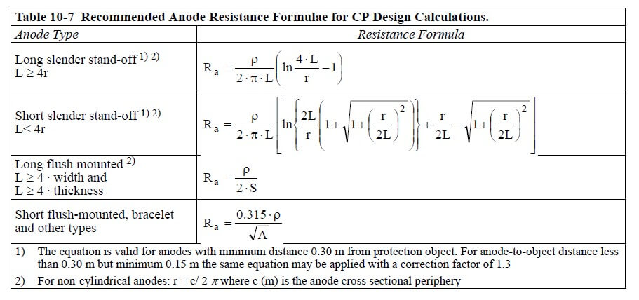
Resistance formulae for different anode types (Source: DNV RP-B401)
From the above formulae, we can see that the resistance depends on the anode dimensions. Now, as the anode is consumed by usage, its mass depletes, and the final dimensions of a completely used anode will be smaller compared to the time it was installed new. Thus, the resistance in the initial and final conditions of the anode will be different.
4.4.2 Current output of anode
The current output of anode is the amount of current which one anode produces. From basic electricity concepts, the current produced by one anode when it is connected to the surface (the cathode), is given by
IA = (Potential difference)/Resistance of anode = ∆E/Ra
Here, potential difference is the electrochemical potential difference between the anode and the surface which it protects. For example, if the surface material is mild steel and the anode is Zinc, then the potential difference is
∆E = (Design potential of mild steel) – (Design potential of Zinc)
Design potential of mild steel = -0.8 V
Design potential of Zinc = -1.05 V
IA = ∆E/Ra = (1.05 – 0.8) /Ra
As explained above, since the resistance of the anode is different in initial and final conditions, this implies that the current output of the anode will also be different in the initial and final conditions. If the resistance of the anode in initial and final conditions is represented by Rai and Raf respectively, then the initial and final current capacity are given by
Initial Current Capacity of Anode, Iai = ∆E/Rai
Final Current Capacity of Anode, Iaf = ∆E/Raf
4.4.3 Anode utilization factor
The whole mass of an anode may not be really utilizable for cathodic protection. After the anode depletes to a certain extent, its effectiveness becomes unpredictable. Thus, only a net mass of the anode can be utilized for cathodic protection. The fraction of anode mass which is actually usable is called the anode utilization factor. This factor depends on the geometry and shape of the anode, and recommended values are provided in the DNV-RP-B401
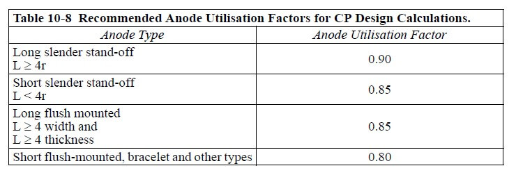
Recommended Anode Utilization Factors (Source: DNV-RP-B401)
4.4.4 Anode Electrochemical Capacity and Closed Circuit Potential
These properties have been discussed before. Electrochemical capacity signifies the rate at which the anode material will be consumed. It is measured in Ampere-hr/kg. Basically, it measures the amount of material which will be consumed to produce a one Ampere current for 1 hr.
Closed circuit potential is the potential at which the anode will be when connected in a circuit to the cathode. Basically, the Steel surface is at a potential of -0.8 V while the anode is at a more negative potential.
The Electrochemical capacities and closed circuit potentials of Aluminium and Zinc anodes can be taken from DNV-RP-B401 and presented below.

Anode electrochemical capacity and closed circuit potential (Source: DNV-RP-B401)
4.4.5 Current capacity of anode
Now we will discuss a property called the current ‘capacity’ of the anode. This is different from the current output of the anode. Current capacity is the amount of current which the anode can produce over its lifetime of usage. Thus, it depends on the amount of material the anode carries, i.e., its weight. We know by now that the net anode mass usable for cathodic protection is determined by the anode utilization factor.
If the mass of one anode is ma kgs, and its utilization factor is u, then the net usable mass of the anode will be ma x u (kgs)
Now, if the electrochemical capacity of the anode is designated as Ԑ, then Ԑ amperes of current per hour will be generated by per kg mass of the anode.
Thus, the current generated by the net mass of the anode will be
Ca = ma x u x Ԑ
This is called the current capacity of the anode, and denotes the amount of current per hour it can produce over its lifetime.
4.5 Calculation of number of anodes needed
Now that we are through with the concepts above, we can get into the actual calculation of number of anodes. Understanding the calculation is relatively simple.
Let the minimum number of anodes required be N.
- Step 1 – On one hand, we have a structure to be protected. We know the area of the structure. Depending on the coating properties and environment, we can get the coating breakdown factor and the current density for the structure from DNV-RP-B401
- Step 2 – Next, we can calculate the total current demand of the structure. There is Initial, Final and Mean current demand. They are denoted as Ici,, Icf and Icm
- Step 3 – calculate initial and final anode current outputs. Earlier we calculated the initial and final current outputs of the anode, denoted by Iai and Iaf
- Step 4 – The initial current demand is basically current required to initiate Cathodic Protection in the new structure. Thus, all the anodes combined together should produce enough current to overcome the current demand. To overcome initial current demand, the total initial current output of N anodes should be more than I Putting this in a relation form, we can write
N x Iai >= Ici ……………………….Equation 1
- Step 5 – Similarly, the final current demand is basically current required to initiate Cathodic Protection in the structure with depleted anodes. Thus, all the anodes (in depleted condition) combined together should produce enough current to overcome the current demand. To overcome final current demand, the total final current output of N anodes should be more than I Putting this in a relation form, we can write
N x Iaf >= Icf ……………………….Equation 2
- Step 6 – Calculate individual anode current capacity. The current capacity of the anode is given by
Ca = ma x u x Ԑ (in Ampere-hr)
ma can be obtained from the anode’s catalog, while u (anode utilization factor) and Ԑ (electrochemical potential) can be obtained from the DNV-RP-B401.
- Step 7 – Calculate the total required current output of anodes. The required mass of anodes should be sufficient to supply the mean current demand over the design life of the anodes.
Let the design life of anodes be tf years. In hours it comes to tf x 8760 (1 yr has 8760 hrs)
The mean current demand of the structure is Icm Amperes.
Thus, total required current demand over the design life of anodes = Icm x tf x 8760
- Step 8 – Calculate the total required anodes to meet required mean current demand.
The total current capacity from all anodes over design life of anodes = Ca x N
The total current capacity should be more than the demand. Thus,
Ca x N >= Icm x tf x 8760 ……………………….Equation 3
Thus, we see that the total number of anodes should be able to satisfy the equations 1, 2 and 3 simultaneously.
- The total initial current output of anodes should be more than the initial current demand of the structure
- The total final current output of anodes should be more than the final current demand of the structure
- The total mean current capacity of anodes should be more than the mean current demand of the structure
Based on above guidelines, we can calculate the minimum number of anodes required, N.
Section 6 – Step-by-step guide for selecting Anodes for Cathodic Protection of your structure
In this section, we summarize all the steps which will be needed for you to plan the cathodic protection of your structure using sacrificial anodes.
- Step 1 – Study the surface to be protected. The shape, size and geometry of the surface affects the anodes to be selected. Get the following parameters of the surface
- Area of the surface
- Material of the surface
- Closed circuit potential of the surface material. Different categories of steel may have different potentials
- Coating category. See DNV-RP-B401
- Step 2 – Study the environment in which the surface is going to experience corrosion. Following parameters of the environment should be obtained
- Salt water or fresh water
- Salinity of water – affects resistivity
- Water depth – affects current demand
- Temperature of environment in which structure will operate – affects the resistivity of anodes and current demand
- Step 3 – Select the anode type to be used
- Select Anode material
- Zinc and Aluminium are widely used.
- Aluminium has better anode properties compared to zinc
- However, zinc is more effective in certain environments with low oxygen
- Aluminium has height restrictions when used in cargo tanks of tankers
- Select anode shape and size – it can be rectangular, tear shaped, cylindrical or other shape based on the operational requirements of the structure
- Accessibility, availability of space and ease of installation are important factors
- For example, for a ship hull, Tear shaped anodes will have lower drag compared to block shaped ones
- The number of anodes will be less for bigger anodes, but installation may be difficult, and they may lead to high point loads. Accessibility and availability of space are equally important considerations
- Select anode mounting method
- Can be slender stand-off, flush mounted, or bracelet etc.
- Slender stand-off anodes have better utilization factor compared to flush mounted.
- Flush mounted anodes may be more preferable for outer hull due to relatively better drag properties.
- Select Anode material
- Step 4 – Get all the anode properties for the selected anode
- Design life
- Electrochemical Capacity
- Closed Circuit Potential
- Anode dimensions
- Step 5 – Calculate the initial, final and mean current demands of the structure to be protected
- Get coating breakdown factors from DNV-RP-B401 based on coating type
- Get the current densities from DNV-RP-B401
- Calculate the initial, final and mean current demands from the current densities and coating breakdown factors.
Ici = ici x fci x AC, Icm = icm x fcm x AC, Icf = icf x fcf x AC
- Step 6 – Calculate the initial and final current output of each anode
- Get anode utilization factor and resistivity from DNV-RP-B401
- Get the anode dimensions from anode catalog
- Calculate the resistance of each anode
- Calculate the initial and final resistance of the anode, Rai & Raf
- Calculate the difference in electrochemical potential between anode material and the protection surface material, ∆E
- Calculate the initial and final current outputs of anode using formula
Iai = ∆E/ Rai , Iaf = ∆E/ Raf
- Step 7 – Calculate the current capacity of each anode
- Get anode utilization factor and electrochemical capacity from DNV-RP-B401
- Calculate current capacity of each anode as
Ca = ma x u x Ԑ (in Ampere-hr)
- Step 8 – Calculate the mean current demand of the structure
- Get the design life of anodes from the catalog, tf
- Get the mean current density from DNV-RP-B401, Icm
- Mean current demand = Icm x tf x 8760
- Step 9 – Calculate the number of anodes needed (N), by satisfying all the following conditions
N x Iai >= Ici
N x Iaf >= Icf
Ca x N >= Icm x tf x 8760
There are other important topics related to anodes, viz.
- Installation of anodes
- Replacement of anodes – when and how?
- Anode Quality testing
Considering the vastness of the material to be covered in these topics, we will cover them in later articles.
References and Links:
- DNV RP-B-401
- http://www.sintef.no/globalassets/upload/materialer_kjemi/anvendt-mekanikk-og-korrosjon/faktaark/corrosion-protection-web.pdf
- http://www.performancemetals.com/anodes/AnodeFAQs.shtml
- http://www.cruisingworld.com/how/zinc-and-aluminum-sacrificial-anodes
- http://www.mcpsltd.com/tankanodes.html
- http://www.etc-cps.com/app_marine.htm
- http://www.amteccorrosion.co.uk/cathprotguide.html
- https://www.eagle.org/eagleExternalPortalWEB/ShowProperty/BEA%20Repository/Rules&Guides/Archives/2_SteelVesselRules2000/Part5VesselTypesCh1_6
- http://www.calqlata.com/productpages/00057-help.html
- http://www.pangolin.co.nz/node/19
Disclaimer: This post is not meant to be an authoritative writing on the topic presented. thenavalarch bears no responsibility for any incidents or losses arising due to the use of the information in this article in any operation. It is recommended to seek professional advice before executing any operation which draws on information mentioned in this post. All the figures, drawings and pictures are property of thenavalarch except where indicated, and may not be copied or distributed without permission.
PS: www.thenavalarch.com has its own spreadsheet app for calculating the number of anodes needed for protection. It is based fully on DNV-RP-B401. You may wish to check it out below.

One of our client is asking for Cathodic protection System for underground SS 316 Mechanical Screen Bars with input salinity of 6000 mg/lit. The size of the mechanical bars is around 3000 mm X 7000 mm. The design current density should be less than than 0.4 mA/m2 and cathodic potential of 250 mV with Zn/Zn sulfate should be achieved complying IEEE 100 and ANSI 42-100 standards and NACE standards. The system should be combination of Sacrificial and impressed current. The protection life should be at least 25 years. Can you please quote the rough cost of system design with brief technical details.
Hi Yasir
Thanks for your query. Would you mind dropping us an email to info@thenavalarch.com?
Hi Team Naval,
I really appreciate your efforts that you wrote a great guide on Cathodic Protection and Sacrificial Anodes, This helped me a lot in my subject.
Going to share this awesome guide in my circle
Thanks for This 🙂
Hi Steven
Apologies for the delay in reply. Glad to be of help. Please do keep visiting!
Hi Steven
Thanks for the appreciation. Please do keep visiting
I have the calculations quantities according to the type of anode. Since I bought your file.
what distance i place the anodes between them?
For small structures such as seachest, rudder etc where current requirement for cathodic protection(CP) is low. CP design for long period say 5 years results in having a CP system where total anode current output is very high as compared to current required by cathode(rudder, seachest). Will this result in excessive consumption of anodes, leading to shortening of design life of anodes. If yes, how to ensure that the anodes last the design life.
Thank you for spending your time to explain a complicated calculation as simple as this.
Can we use the same method of calculation for other parts such as sea chest, side thruster, rudder etc.?
Thanks in advance 🙂
Hi Abdullah
The method can be used for any surface exposed to sea.
Can you give the current density requirement for protection of rudderand thruster tunnel of ship
Hi Philip
Please can you write in detail to info@thenavalarch.com? We’ll get back the soonest
Hi there, I have a question about anodes. I have a vessel that is bare metal (steel) no more antifouling. And there come a question if I fix more anodes than required is it possible to make more damage to the steel?
How to check for optimum cathodic protection
Hi Ramakrishnan
You can follow DNV-RP-B401 for the calculations. We too have an app for the same:
https://thenavalarch.com/software/maritime-industry-thenavalarch/ship-design/ship-corrosion/sc-1-cathodic-protection-design-spreadsheet/
Hello,
I want to install sacrificial Zinc Anodes (each 15 kg) for Khukri ship. Length of ship is 91 meters and water depth 3.80 meters so please suggest me the number of anodes to be installed and pattern.
Please reply me on my mail.
Thanks & Regards
Ashish Kumar
Dear Ashish
Thanks for your query. You can use our cathodic protection design spreadsheet, or you can follow DNV-RP-B401 and do your own formulation
https://thenavalarch.com/software/maritime-industry-thenavalarch/ship-design/ship-corrosion/sc-1-cathodic-protection-design-spreadsheet/
Regards
Please I did a SACP design for a Barge Hull and Ballast Tanks using DNVGL-RP-B401 2021. Please I wish to know how to distribute/install the sacrificial anodes.
Hull – SA = 1440.2 square.meters, L = 76 m, W = 24.5 m, Draft = 2.5 m, Number of anodes = 271. I am thinking 60% should be mounted on the Stern, 40% (i.e., 20 % on each side) shall be distributed at the left and right side of the Hull up to the Bow. Please I will appreciate feedback on the anode distribution mechanism.
Likewise, for the internal ballast tanks.
Ballast Tank 1, Length -14 m, Width – 7.75 m, Height – 3.67 m, Volume @ 98% – 397.7 cubic. Meters, calculated number of anodes = 61. I am thinking since it’s a box filled with 98% vol. fresh water, anodes distribution should be a combination of wall and ground plate mounted.
Please I will be grateful if someone can help with my enquiry, reference documents and drawings will also be helpful.
Thank you in advance.